NOVI GUI User GUIDE
NOVI API provides the experimenters with RESTFul web services to access NOVI functionalities. However, in most of the cases experimenters do not want to call these services directly, since, for example, assembling a virtual topology request may be a tiresome business. To make the usage of NOVI toolkit easier, two graphical user interfaces have been developed for two different pusposes: 1.) Slice Editor for creating, removing and managing slices. 2.) Monitoring GUI to obtain different characteristics of the virtual resources in the experimenters’ slices.
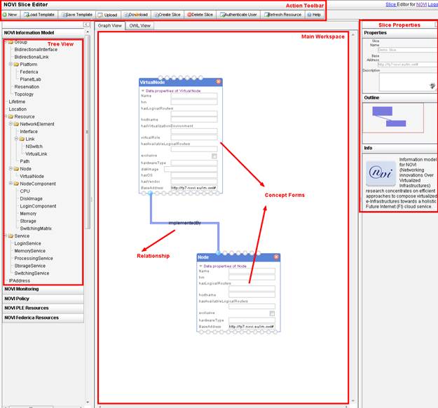
Figure 21:
Slice editor
The slice editor
depicted in Figure 21 is designed for composing slice using
NOVI-IM. The Slice Editor evolved from the Ontology Instance
Editor – OIntEd [OINTED] which was originally used to assist in the
development phase of the NOVI IM and subsequently was customized to allow users
to handle slices. In the left side
of the editor there is a tree view which shows the hierarchy of concepts from
NOVI-IM which can be used for slice composition. User can use the nodes of this
tree to compose their request, by dragging them to the main GUI Graph View
workspace, which is located in the center of the slice editor.
A concept dragged
from tree view into the main workspace will instantiate a form. Editable fields
from a concept will be provided to user, so they can fill in related data
properties. At the bottom of each concepts, there are ports for defining
relationship among concepts. Connecting a wire from these ports to another
matching ports in another form defines relationships among these concepts.
After user is
done with composing their slice, an OWL representation of these composed slice
can be seen on OWL View of the workspace. This view is an uneditable textual
representation of the graphical composition provided in the Graph View. This is
the resulting OWL that will be send to the NOVI service layer.
On the right hand
side of the editor there are some additional information about property of a
slice, an highlevel outline view of the graph that is currently being composed,
and some other information.
The toolbars at
the top of the editor provides main operations that user can apply to the
composed slice. User can create new slice using the top left new button, load
and save template to the GUI backend. User can also upload and download OWL
file created using this editor.
Buttons on right
side of the tool bars are for interacting with NOVI service layers. Create
slice and delete slice can be used to create and delete slice which is created
with current user. Authenticate user button will allow user to authenticate by
giving user name and password of his/her account at the experimental
platform he/she is registered at.
Refresh resources will let user update the list of resources which are
authorised and available for him. These resources will currently be shown on
the NOVI PLE Resource and NOVI Federica Resources tab on the tree view/left
side of the editor.
In this
experimenters guide for using slice editor we will describe by example how to
use the slice editor. In the example we will show detailed steps required to
perform the following operations: (i) authenticate (ii) create virtual
resources mapped or not to phsyical ones and (ii) create a slice request.
1.1.1.1 Authentication
Authentication is required to perform any slice management operation via the NOVI Slice Editor. Currently, password authentication is supported, using the credentials of the user at the experimental platform he/she is registered at. Selecting the "Authenticate user" button will allow the user to provide the necessary authentication information to log in the NOVI federation (Figure 22 and Figure 23).
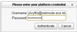
Figure 22: Provide Username and password
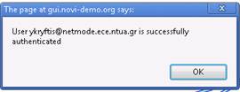
Figure 23: Successfully authenticated
An
authenticated user retrieves the list of all slices that he/she ownes (Figure
24). Via clicking on the "Refresh
Resource" button, the user has the ability to reterieve the list of
physical resources that he/she is authorized to use across the set of NOVI
federated platforms (Figure
25). Specifically the Uniform Resource Names
[URN] of the pshycial resources are presented.
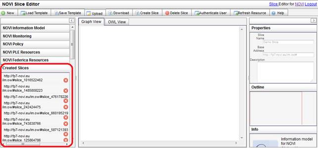
Figure 24: Created Slices for authenticated user
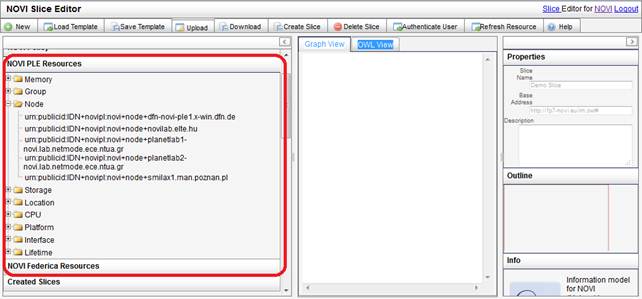
Figure 25: Listing Resources for authenticated user
1.1.1.2 Building Blocks
In this
section, we will show how we can compose resource request using the slice editor.
In this subsection we will explain about how we can compose the required
building blocks that can be used to compose a complete slice request. We will
show step by step how we can instantiate these building blocks, and then we can
see in the following subsection how we can combine these building blocks in
order to create complete slice.
1.1.1.2.1
Topology
Container
All
requests must be contained within a topology. Thus all the building blocks that
will be described in the following page, we need a topology as a container.
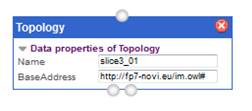
Figure 26: Topology
We
instantiate a topology by dragging Topology concept from tree view at the
leftside of the GUI, and filling in the name of the slice we would like to
request. This topology will contain
all the rest of the building blocks.
In the
subsequent steps we need to declare that all other resources we compose are
part of this topology, by connecting them to the ‘contains’ port at
the bottom of the Topology object. Example of declaring that a VirtualNode is
contained within a topology is shown in the following figure:
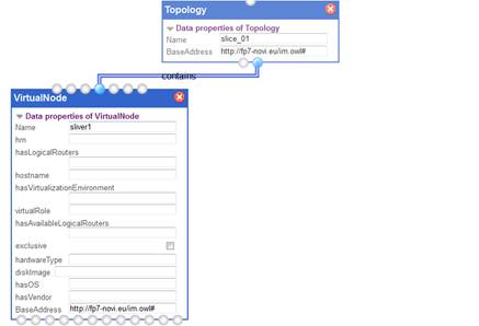
Figure 27: Topology Contains Virtual Node
1.1.1.2.2 Virtual Node
VirtualNode
can be instantiated by dragging virtual node from the treeview of concepts. In the
same way that we instantiated topology, we give this virtual node a name and
then we can fill in its properties.
We can
express non-functional requirements for each virtual node that we compose. This
is done by defining the the virtual node’s component properties. A
virtual node can have CPU (GHz), Storage (GB) and Memory (GB) as components,
and for each of these components we can require certain properties to be
satisfied. We also can express
fucntional requirements for the virtual node such as virtualization enviroement
and OS, that are properties of the node.
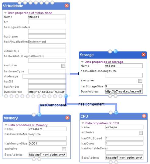
Figure 28: Virtual Node with Components
In Figure 28,
we define a virtual node with storage size 5 GB, CPUSpeed 1 GHz, 1 core, and a
1 MB memory. Every virtual
node also can have virtual interfaces, and for each of these interfaces we need
to define if they are outbound or inbound interfaces. In the following fidure
we provide inbound and outbound interfaces for virtual node sliver1
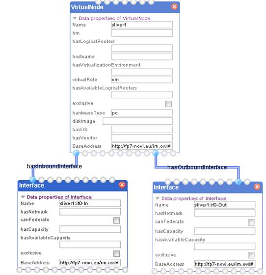
Figure 29: Virtual Node with Interfaces
1.1.1.2.3 Bound Node
Bound Node
is composed by defining the mapping of a virtual node - that is the required
physical node that will host the virtual one. The virtual node first can be
defined in the same manner as we defined Virtual Node in the previous sections,
and then an additional Node concept can be instantiated. The value/name of this
physical node should be one of the resources that is authorized/available for
current user, which can be seen on the treeview.
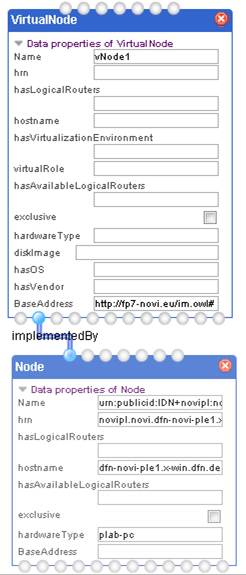
Figure 30: Virtual Node with its Physical Bound Node
1.1.1.2.4 Virtual Link
A link is defined
by composing a VirtualLink object, and connecting related virtual interfaces to
this link. Every virtual link must have source and sink. By default, a virtual
link is an unidirectional link. In the case that we want a bidirectional link,
another virtual link from the matching opposite direction needs to be
instantiatied.
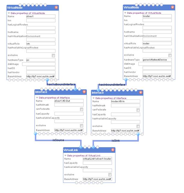
Figure 31: Unidirectional Virtual Link
We can
compose unidirectional virtual link by connecting interfaces of virtual nodes.
Therefore, before we can create a virtual link, we need a source interface,
which should be an outbound interface of a virtual node, and a sink interface,
which should be an inbound interface of a virtual node.
In the
example of buildling block depicted in Figure 31, the source virtual node is the
sliver1, which has sliver1:if0-Out as its outbound interface. This interface
will then become a source of the created Virtual link. While the sink virtual
node is lrouter, having lrouter-if0-in as inbound interface. This last
interface is the sink of our virtual link.
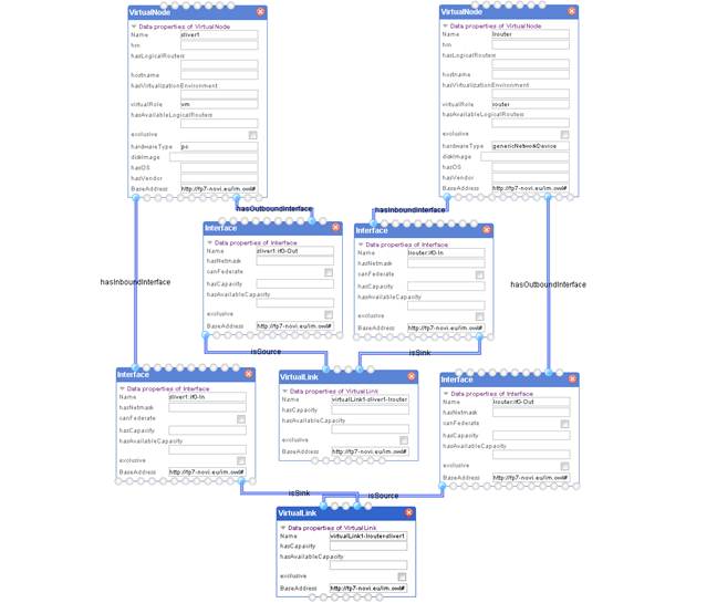
Figure 32.a: Bidirectional Virtual Link
1.1.1.2.5 Bound Link
A bound link can then be provisioned by a phsysical path. In order to compose a bound link, we need first to make sure that all interfaces contained the virtual link that we wanted to provision is implemented by a physical interface. Once we are done with this then we can create a Path object which provisioned this link.
Path is conceptually a container, in which we need to specify interfaces involved in provisioning the link, and also NOVISwitch that is required to provision the virtual link. In figure 32.b we can see an example of how the previous bidirectional virtual link from Figure 32.a is provisioned. Each interfaces in original virtual link are implemented by a corresponding physical interface. Both virtual link are provisioned by a path, one direction from path1-sliver1-lrouter and the other direction path1-lrouter-sliver1
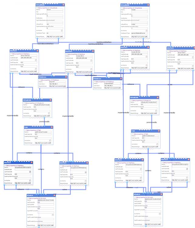
Figure 32.b : Bound Bidirectional Link
1.1.1.2.1 Platform Bound Resource
A platform bound resource is composed by defining the assignement of the virtual resource to a platform in the NOVI federation. The virtual node first can be defined in the same manner as we defined Virtual Node in previous sections, and then an additional Platform concept can be instantiated. The Platform concept, similar to the Topology concept, will "contain" the virtual resources. In the following figure, the example of a platform bound (in PlanetLab) virtual node is provided.
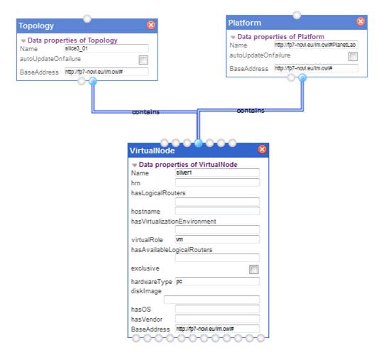
Figure 33: Bound Bidirectional Link
1.1.1.3 Slice Composition
The
building blocks explained in the previous subsection can be used to compose slice
request. There are three types of requests that we can create: unbound
requests, bound requests, and partial (platform) bound requests. In unbound
requests all the resources required are virtual resources, thus we can use
virtual node and virtual link as a building block.
In bound
requests, all of the requested resources are implemented by physical resources
that are authorized for the current user. As an illustration, we will show in
the following example how we construct unbound requests using the building
blocks.
1.1.1.3.1 Unbound Request
Figure 34: An example unbound topology
In this example, we are
going to compose unbound topology as depicted in Figure 34. The requested virtual topology is
comprised of two virtual nodes, vNode1 and vNode2 and a logical router, with
specific non-functional requirements, (sliver1: Disc Space: 8GB; CPU speed:
2GHz; CPU cores: 2; Memory Size: 2GB) and (sliver2: Disc Space: 10GB; CPU
speed:2GHz; CPU cores: 2; Memory Size: 2GB).
The
following unbound requests can be constructed using three virtual nodes, one of
which is composed as logical router. The nonfunctional characteristics for each
of these virtual nodes should be specified following examples in building block
(Figure 28). Since the virtual links are
bidirectional we need to use bidirectional virtual link building blocks as
exemplified in Figure 32, one of these building block for
each of the virtual link1, and virtual link2.
In the
Slice editor, each of these building block will be combined into one single
request, without repeating intersecting components on each of these building
block. One additional step to bind together all these building block is to instantiate
a topology container as explained in Section 4.3.1.2.1 to contain all resources involved in
these building blocks. The resulting request can then be submitted to the NOVI
service layer using create slice button.
1.1.1.3.2 Bound Request
Figure 35: A
bound request example
The requested virtual topology is comprised of
two virtual nodes, vNode1 and vNode2, with specific functional/non-functional
requirements (see Figure 35), (vNode1: Hardware
Type: Disc Space: 10GB; CPU speed: 2GHz; CPU cores: 4; Memory Size: 1000MB) and
(vNode2: Hardware Type: Disc Space: 30GB; CPU speed:3GHz; CPU cores: 2; Memory
Size: 500MB). vNode2 is mapped to smilax1.man.poznan.pl and vNode1 to planetlab1-novi.lab.netmode.ece.ntua.gr.
This type of requests can be composed using two
bound Node building blocks that is explained in Section 4.3.1.2.3 (Figure 30). The
non-functional characteristics should be supplied using node component as
exemplified in (Figure
28).
1.1.1.4 Slice Creation
After
finished composing the slice that we want to request, we can send the composed
slice to NOVI service layer by clicking “Create Slice” button from
the action toolbar in the slice editor. A user feedback page will be presented
that will provide information about steps involved in the slice creation
process. If slice creation is successful, the last bit of information in the
user feedback page will shows the information about slice created.
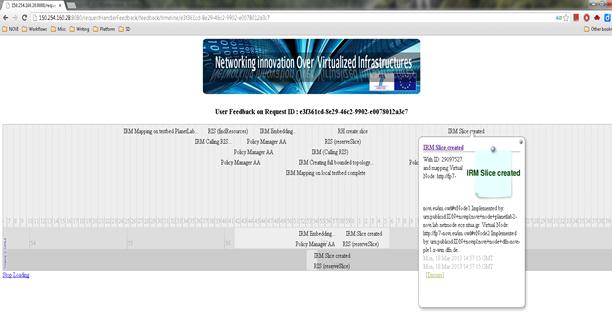
Figure 36: Slice Creation
1.1.1.5 Slice Deletion
If user is
authenticated, then he can see the slices that he already created. He can then
select the slice that he wanted to delete, and perform deletion.
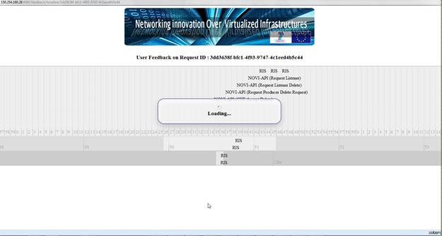
Figure 37: Slice Deletion